 | |
| |
| Doc.Fleming | |
| Chron. télégraphes | |
| Chron. téléphone | |
| Chronologie radio | |
| Chronologie comp. | |
| Index Scientifiques | |
| Bibliographies |

|
Sir
John Ambrose Fleming
|
||
|
DOCUMENTS
|
||
N 24,850
A.D. 1904 |
||
Improvements
in Instruments for Detecting and Measuring Alternating Electric
Currents. |
||
Page number 1
PROVISIONAL SPECIFICATION. Improvements in Instruments for Detecting and Measuring Alternating Electric Currents. I JOHN AMBROSE FLEMING of University College, Gower Street, in the County of London, Doctor of Science, do hereby declare the nature of this invention to be asfollows: - It is
well known that alternating electric currents can only bedetected and
measured by the use of some instrument, the indications of which do not
depend upon the direction of the current. Hence an instrument of which
the indication is dependent upon the heating of a wire by the current
commonly known as a hot wire instrument is suitable for the above
purpose. Also one depending upon- the attraction or repulsion of
electric current, commonly known as an electro- dynamometer, because in
both these cases the indication or reading of theinstru- ment is tho
same even if the current direction is reversed.
On the
other hand, an ordinary galvanometer of the movable needle or movable ,
coil type cannot by itself be used for detecting or measuring
alternating currents because it only gives an indication with a
unidirectional current and is therefore unaffected by an alternating
current.
The
object of my invention is to provide a means by which an ordinary
galvanometer can be used to detect and measure alternating electric
currents and cspecially high frequency alternating currents commonly
known as electricoscüla- tions.
The means
I employ for this purpose consists in the insertion in the circuit of
the alternating current of an appliance which permits only the passage
of electric current in one direction and constitutes therefore an
electrical valvc.
I
construct it as follows: -In ,a glass bulb, I seal two or more carbon
filaments such as a.re used for the manufacture of electric lamps.
These filaments eachhave their own separate terminals. One or more of
these carbon filaments may be replaced by loops of platinum wire,
provided at least one carbon filamentis. used. A high vacuum must be
made in the bulb. Two such bulbs are employed and for the sake of
simplicity, I may describe the mode of use when a double carbon
filament. in eachbulb is used. The two bulbs arc each associated with a
small insulated primary or secondary battery of sufficient voltage to
bring one of the filaments to bright incandescence of greater intrinsic
brilliancy than if used -as an incandescent lamp.
The bulbs
are connected in parallel with each other and inserted in the
alternating current circuit, but so that an incandescent filament and a
dark or cold filament in each. bulb form the electrode or connection
for the current to be measured to enter and leave the bulb.
. In
series with one of the bulbs is placed anordinary galvanometer. In the
two branch circuitsformed of the two bulbs, one in series with a
galvanometer the local insulated batteries arc arranged to ignite
carbon filaments at opposite ends.
That is
to say, the carbon filadioiif-nearest to one common terminal is the
ignited filamerit in one bulb and that farthest from the same common
terminal in the other bulb.
|
||
| |
||
| Page number 2
These
bulbs have the property that inside the bulb, negate electricity can
move from the hot to the cold carbon filament even under a very low
electromotive force but it cannot move in the opposite direction.
Hence, owing to the arrangement of the bulbs, the alternating current
arriving at the common terminal splits and all the positive
alternations pass through one bulb and all the negative through the
other bulb.The galvanometer is thereforea-ffected solely by currents
flowing in one direction. The bulbs serve the purpose of separating out
the two constituents of the alternating current.
In place of two bulbs, one only may be used in series with a galvanometer and then the bulb only allows currents to pass in one direction and the galvanometer gives an indication. The device is especially applicable to the detection and measurement by an ordinary galvanometer of high frequency electric currents or oscillations. where any form ofmechanical or electrolytic rectifier is useless. ' I construct the bulbs with two or more sets of carbon filaments. Ono set when rendered incandescent forming one electrode of the valve and the other set kept cold, the otherelectrode. In place of carbon filament for the cold electrodes I use sometimes, loops of platinum wire or platinum wires with plates on the end. In making
the connections of the bulb to the alternating current circuit it is
essential to join one end of the galvanometer wire to that terminal of
the hot carbon filament to which the negative end of the local or
heating battery isapplied.
The other end of the galvanometer and the two ends or all the ends of tho cold</RTI> filaments taken together constitute the terminal of the indicating appliance. The carbon filament may also be heated by part of the alternating current which is being rectified or measured. Any other method of heating one or more of the carbon filaments muy be employed. The above described multiple carbon filament bulb and a galvanometer may be used as a receiving instrument in wireless telegraphy. . For this case, the aerial receiving wire has the primary circuit of an oscillationtransformer inserted in it and one of the above described electrical valves and agalvanometer arc inserted in the secondary circuit. The feeble alternating currents excited in the aerial by electric waves, then make themselves evident by Indications in the galvanometer. COMPLETE SPECIFICATION. @ Improvements in Instruments for Detecting and Measuring Alternating Electric Currents." I,
JOHNAMBROSE FLEMING, of University College, Gower Street, in the County
of London, Doctor of Science, do hereby declare the nature of this
invention and in what manner the same is to be performed to bo
particularly described and ascertained in and by the following
statement:---
This
invention relates to certain new and useful devices for converting
alternating electric currents and especially high frequency alternating
electric currents or electric oscillations into continuous olectric
currents for the purpose of making them detectable by, and measurable
with, ordinary direct currentinstru- ments such as a
"mirrorgalvunometer"of the usual type or any ordinary direct current
ammeter. .. ~
|
||
< Page number 3>
Such
instruments as the latter are not affected by alternating electric
currents either of high or low frequency which can only be measured and
detected by instruments called alternating current instruments of
special design. It is, however, of great practical importance to be
able to detect feeble electric oscillations, such as are employed
inI3ertzian wave telegraphy by an ordinary movable coil or movable
needle mirror galvanometer. This can be done if the alternating current
can be ".rectified ", that is either suppressing all the constituent
electric currents in one direction and preserving the others, or. else
by changing thedirec- tion of one of the sets of currents which compose
the alternating current so that the whole movement of electricity.is in
one direction. Many means have been devised and are in use for
rectifying low frequency alternating currents, such as are used in
electric lighting. There are well known forms of mechanical rectifier',
also there is a well known form of electro-chemical rectifier depending
on the fact that when a plate of carbon and aluminium is placed in any
electrolyte which yields oxygen on electrolysis, an electric current
can only pass through this cell in one direction if below a certain
voltage.
Both these forms of rectifier are however inapplicable for high frequency currents. I have found that the aluminium-carbon cell will not act with high frequency currents. I have
discovered that if two conductors are enclosed in a vessel in which a
good vacuum is made, one being heated to a high temperature, the space
between the hot and cold conductors possesses a unilateral electric
conductivity, and negative electricity can pass from the hot conductor
to the cold conductor but not in the reverse direction.
As the
hot conductor should beheated to a very high temperature say near to
the melting point of platinum(1700 ' C. ), it should be of carbon
preferably in the form of a filament such as is used in any ordinary
incandescent electric lamp. The cold conductor may be of many
materials, but I prefer a bright metal such:is platinum or aluminium or
else carbon.
The two
conductors arc enclosedin' a glass bulb similar to that of an incan-
descent lamp, and I generally heat the carbon filament to a high state
of incan= descence by atcontinuous electric current, the electrical
connection to the filament and the cold conductor being made by
platinum wires, sealed air tight through the glass.
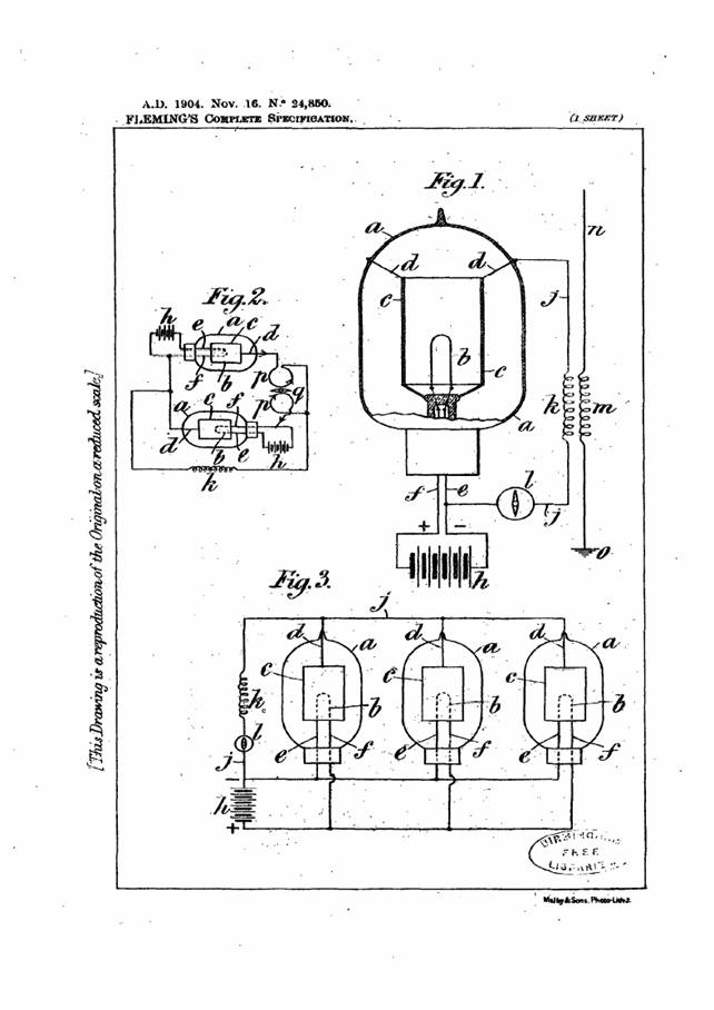
Figure 1 is a full size sectional elevation ofan instrument constructed according to this invention, the electrical connections being shown diagrammatically. This figure illustrates the application of the invention to wireless telegraphy. Figures 2 and 3 show modifications to smaller scales. In Figure
1 a is a glass bulb, andb is a carbon filament like the carbon
fila-inent of an incandescent lamp, suitable say for taking a current
of G to 8 volts and 2 to 4 amperes. c is a cylinder of aluminium open
at the top and bottom which surrounds but does not touch the filament.
The cylinderc is suspended and steadied by platinum wiresd, and the
ends of the filament6 are connected to platinum wires connected to the
leads e and f. The platinum wires are sealed through the glass in the
ordinary manner.
As a very
high vacuum should be obtained in the bulba and as a considerable
quantity of air is occluded in the conductors these should be heated
when the bulb is being exhausted. The filament b can be conveniently
heated by passing a current through it whilst the cylinder c can be
heated by surrounding the bulb a with a resistance coil through which a
current is passed the whole being enclosed in a box lined with asbestos
or the like. When as hereinafter described the cylinder c is replaced
by any form of conductor which can be heated by passing a current
through it this method is usually more convenient than that just
described.
The
carbon filament is made highly incandescent in the usual way by a
continuous electric current produced by thebattery h. the negative pole
of which is connected to the wire e and the .positive to the wire f.
The wires d and e are
|
||
|
<Page
number 4>
connected together by a wire jwhich completes the circuit through the secondary winding k of an induction coil (such as is ordinarily used in wireless telegraphy) and a galvanometer l. m is the primary winding of the induction coil having one end connected as is usual to an aerial wire n and the other to earth o. The arrangement described above operates as an electric valve aiid permits negative electricity to flow from the hot carbon b to the metal cylinder c but not in the reverse direction so that the alternations induced in the coil k by theHertzian waves received by the aerialwire n are rectified or transformed into a more or less continuous current capable of actuating the galvanometer l by which the signals can be read. Although Figure 7 shows the application of the instrument to wirelesstele-- graphy it will be understood that the aerialwire ? may be replaced by any circuit in which there is an alternating electromotive force, whether of low frequency or of high frequency. I may increase the effect in the following manner:-1 employ two bulbs arranged as shown in Figure 2 each being similar to that shown in Figure 1. p p are the two coils of a differential galvanometer connected to the bulbs in such fashion that currents flowing in opposite directions through the two bulbs, flow in the same direction round the two coils of the galvanometer as regards the needle q of the galvanometer itself. For this purpose the hot conductor of each bulb is connected to the cold conductor of the ,other,hence, one bulb permits negative electricity to flow only in one direction and the other bulb permits only negative electricity to flow in the opposite direction through it. The common terminal of the two galvanometer coils p is connected to the coil k or any source of alternating electromotive force or of ,electrical oscillations, the other terminal of the said source being connected to the bulbs as shown. Each bulb has its own separate insulated battery It, for heating its hot filament. Under these circumstances, alternating electric currents are split into two continuous currents passing through the two bulbs in opposite and, in the two coils of the galvanometer, in the same directions. By thus using a differential galvanometer I make use of the whole of the energy of the alternating current instead of discarding half of it. In this manner very feeble electrical oscillations can make themselves apparent by the indication which they give on a sensitive mirror galvanometer. A number of these valves may be associated together in parallel as shown in Figure 8 so that alternating currents rectified by them separately may produce continuous currents which are added together. In place of using a metal cylinder surrounding a carbon loop filament, I sometimes use a number of carbon filaments. Some of these are heated, by means of an electric current, and become the hot conductor of the oscillation valve and the others remain cold and form the cold conductor. Or the metal cylinder may be replaced by a cylinder of meerschaum or the like having wound helically upon it a narrow ribbon of metallic foil. The galvanometermay be replaced by any other instrument fordetecting the oscillations or by a relay for actuating a detecting or recording instrument. In those cases in which a larger alternating current has to be dealt with, the hot conductor may be a rod of soft graphitic carbon held in suitable supports. I find it possible by means of the device described above to rectify an alter-nating current without the use of any auxiliary continuous heating current. 'Thus, if I pass through thecarbonntamcnt an alternating current to bring it to bright incandescence, I find if I connect either terminal of the filament by a circuit outside the bulb with the terminal of the embracing cylinder or other cold conductor, then in this circuit a continuous current flows. Hence, the device may be used forrectifying either high frequency or low frequency alter- nating currents of electrical oscillations, provided these are of sufficient strength to render a carbonfilmncnt brilliantly incandescent. |
||
| < Page
number 5>
Having now particularly
described and ascertained the nature of my said invention and in what
manner the same is to be performed I declare that what I claimis : -
1.
A vacuous vessel having in it two conductors adjacent to but not
touching each other, one of them being heated, these conductors being
connected by a circuit outside the vessel, such circuit being exposed
to some influence tending to produce an alternating current in it and
which contains a galvanometer or other instrument for detecting a
continuous current substantially as described.
|
||
 |